 |
�� | �� |
|
|
|
|
|
|
|
|
|
| SAE J429 Studs Specification-NINGBO BOLT |
|
|
 |
 |
 |
 |
��
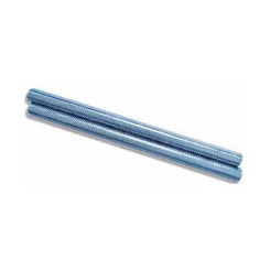
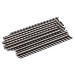
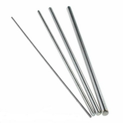
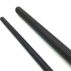
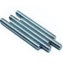
| �� | �� | SAE J429 Tap End Studs Bolts | �� | �� |
SAE J429 Studs Specification
SAE J429 standard covers specifications to chemical, mechanical and other material requirements for inch-series carbon and alloy steel bolts, screws, studs, and U-bolts, used in automotive and related industries in sizes up-to 1-1/2 inch, inclusive.
SAE J429 Grades
|
Grade Designation |
Products |
Nominal Size Range Dia, Inch |
|
1 |
Bolts, Screws, Studs |
1/4 through 1-1/2 |
|
2 |
Bolts, Screws, Studs |
1/4 through 1-1/2 |
|
3/4 through 1-1/2 |
||
|
4 |
Studs |
1/4 through 1-1/2 |
|
5 |
Bolts, Screws, Studs |
1/4 through 1 |
|
Over 1 through 1-1/2 |
||
|
5.2 |
Bolts, Screws |
1/4 through 1 |
|
8 |
Bolts, Screws, Studs |
1/4 through 1-1/2 |
|
8.1 |
Studs |
1/4 through 1-1/2 |
|
8.2 |
Bolts, Screws, Studs |
1/4 through 1 |
SAE J429 Chemical Composition
|
Grade |
Nominal Size, Dia, Inch. |
Material |
C % |
Mn % |
P % |
S % |
B % |
|
1 |
1/4 through 1-1/2 |
Low or medium carbon steel |
0.55 max |
�� |
0.025 max |
0.025 max |
�� |
|
2 |
1/4 through 1-1/2 |
Low or medium carbon steel |
0.15 �C 0.55 |
�� |
0.025 max |
0.025 max |
�� |
|
4 |
1/4 through 1-1/2 |
Medium carbon steel |
0.28 �C 0.55 |
�� |
0.025 max |
0.13 max |
�� |
|
5 |
1/4 through 1-1/2 |
Medium carbon steel |
0.28 �C 0.55 |
�� |
0.025 max |
0.025 max (4) |
�� |
|
Carbon steel with additives (e.g. Boron or Cr or Mn) |
0.15 �C 0.40 |
�� |
0.025 max |
0.025 max (4) |
0.0005 �C 0.003 |
||
|
5.2 |
1/4 through 1 |
Low or medium carbon steel |
0.15 �C 0.25 |
0.74 max |
0.025 max |
0.025 max |
0.0005 �C 0.003 |
|
8 |
1/4 through 1-1/2 |
Medium carbon steel Or |
0.25 �C 0.55 |
�� |
0.025 max |
0.025 max (4) |
�� |
|
Alloy (6,7,8) Steel with additives (e.g. Boron or Cr or Mn) |
0.20 �C 0.55 |
�� |
0.025 max |
0.025 max (4) |
�� |
||
|
Medium carbon (6,7,8) Alloy Steel |
0.28 �C 0.55 |
�� |
0.025 max |
0.025 max |
�� |
||
|
8.1 |
1/4 through 1-1/2 |
Medium carbon alloy (6,7,8) or SAE 1541 steel |
0.28 �C 0.55 |
�� |
0.025 max |
0.04 max |
�� |
|
8.2 |
1/4 through 1 |
Low carbon boron steel (6) |
0.15 �C 0.25 |
0.74 max |
0.025 max |
0.025 max |
0.0005 �C 0.003 |
NOTES :
1. All values are for product analysis (percent by weight). For cast or heat
analysis, use standard permissible varia-tions as shown in SAE J409.
2. For studs only, sulfur content may be 0.33% maximum.
3. For Grades 5 and 5.1, fasteners, medium carbon boron or medium carbon alloy
steels, as specified for Grade 8 fasteners, may also be used at the
manufacturer's option.
4. For studs only, sulfur content may be 0.13% maximum.
5. Grade 5 material heat treated before assembly with a hardened washer is an
acceptable substitute.
6. When the carbon content in boron steel is less than 0.25% the minimum
manganese shall be 0.60% for Grades 5, 5.1, and 5.2 and 0.70% for Grades 8, 8.1,
and 8.2.
7. Alloy steel shall contain at least one of the following elements in the
minimum quantity given: chromium 0.30%, nickel 0.30%, molybdenum 0.20%, vanadium
0.10%, manganese 1.65%. Where elements are specified in combi-nations of two,
three, four, or five and have alloy contents less than those given above, the
limit value to be applied for steel class determination is 70% of the sum of the
individual limit values shown above for the two, three, four or five elements
concerned.
8. When alloy steels are in the "as quenched" condition, prior to tempering, the
microstructure in the core of the threaded section shall be approximately 90%
martensite (refer to Table 3).
9. When boron is added the limits shall be 0.0005% to 0.003%.
SAE J429 Mechanical Requirements for Bolts, Screws and Studs
|
Grade Desig- nation |
Prod ucts |
Nominal Size Dia, In |
Full Size's Bolts, Screws, Studs, Sems, Proof Load (Stress), psi |
Full Size's Bolts, Screws, Studs, Sems, Tensile Strength (Stress) , Min, Ps' |
Machine Test Specimens of Bolts, Screws, and Studs Yield's Strength (Stress) Min, psi |
Machine Test Specimens of Bolts, Screws, and Studs Tensile Strength (Stress) Min, psi |
Machine Test Specimens of Bolts, Screws, and Studs Elongation Min, % |
Machine Test Specimens of Bolts, Screws, and Studs Reduction of Area Min, % |
Surface Hardness Rockwell 30N Max |
Core Hardness Rockwell Min |
Core Hardness Rockwell Max |
|
1 |
Bolts, Screws. Studs |
1/4 thru 1-1/2 |
33,0000) |
60,000 |
36,000 |
60,000 |
18 |
35 |
�� |
B70 |
B100 |
|
2 |
Bolts, Screws, Studs |
1/4 thru 3/40) |
55,0000) |
74,000 |
57,000 |
74,000 |
18 |
35 |
- |
680 |
B100 |
|
Over 3/4 thru 1-1/2 |
33,000 |
60,000 |
36,000 |
60,000 |
18 |
35 |
- |
B70 |
B100 |
||
|
4 |
Studs |
114 thru 1-1/2 |
65,000 |
1,15,000 |
1,00,000 |
1,15,000 |
10 |
35 |
- |
C22 |
C32 |
|
5 |
Bolts, Screws, Studs |
1/4 thru 1 |
85,000 |
1,20,000 |
92,000 |
1,20,000 |
14 |
35 |
54 |
C25 |
C34 |
|
Over 1 thru 1-1/2 |
74,000 |
1,05,000 |
81,000 |
1,05,000 |
14 |
35 |
50 |
C19 |
C30 |
||
|
5.1 |
SEMS |
No. 4 thru 5/8 |
85,000 |
1,20,000 |
- |
- |
- |
- |
60. |
C25 |
C40 |
|
5.2 |
Bolts, Screws |
1/4 thru 1 |
85,000 |
1,20,000 |
92,000 |
1,20,000 |
14 |
35 |
56 |
C26 |
�� |
|
8 |
Bolts, Screws, Studs |
1/4 1/2 ru th 1- |
1,20,000 |
1,50,000 |
1,30,000 |
1,50,000 |
12 |
35 |
59. |
33 |
39 |
|
8.1 |
Studs |
1/4 thru 1-1/2 |
1,20,000 |
1,50,000 |
1,30,000 |
1,50,000 |
10 |
35 |
59. |
C33 |
C39 |
|
8.2 |
Bolts, Screws |
1/4 thru 1 |
1,20,000 |
1,50,000 |
1,30,000 |
1,50,000 |
10 |
35 |
59. |
C33 |
C39 |
Note:
1. See footnote 2 of
the Scope.
2. Yield strength is stress at which a permanent set of 0.2% of gage length
occurs.
3. Not applicable to studs or slotted and cross recess head products.
4. Proof load test. Requirements in these grades only apply to stress relieved
products.
5. Grade 2 requirements for sizes 1/4 through 3/4 in. apply only to bolts and
screws 6 in. and shorter in lengths. For bolts and screws longer than 6 in.,
Grade 1 requirements shall apply.
6. Grade 5 material heat treatment before assembly with a hardened washer is an
acceptable substitute.
7. "Full Size" means a tension test specimen consisting of a completed fastener
for testing in the ready alteration.
SAE J429 Proof Load for Bolts, Screws and Studs
|
Nominal Dia of Product and Threads per in. |
Stress Area, in2 |
Grade 1 |
Grade 2 |
Grade 4 |
Grade 5 & 5.2(2) |
Grade 5.1 |
Grade 8,8.1, 8.2(2) |
|
Proof Load, lb |
Proof Load, lb |
Proof Load, lb |
Proof Load, lb |
Proof Load, lb |
Proof Load, lb |
||
|
Coarse Thread Series UNC |
|||||||
|
No. 6-32 |
0.00909 |
- |
- |
- |
- |
750 |
- |
|
8-32 |
0.0140 |
- |
- |
- |
- |
1,200 |
- |
|
10-24 |
0.0175 |
- |
- |
- |
- |
1,500 |
- |
|
12-24 |
0.0242 |
- |
- |
- |
- |
2,050 |
- |
|
1/4-20 |
0.0318 |
1,050 |
1,750 |
2,050 |
2,700 |
2,700 |
3,800 |
|
5/16-18 |
0.0524 |
1,750 |
2,900 |
3,400 |
4,450 |
4,450 |
6,300 |
|
3/8-16 |
0.0775 |
2,550 |
4,250 |
5,050 |
6,600 |
6,600 |
9,300 |
|
7/16-14 |
0.1063 |
3,500 |
5,850 |
6,900 |
9,050 |
9,050 |
12,800 |
|
1/2-13 |
0.1419 |
4,700 |
7,800 |
9,200 |
12,100 |
12,100 |
17,000 |
|
9/16-12 |
0.182 |
6,000 |
10,000 |
11,800 |
15,500 |
15,500 |
21,800 |
|
1-1/8-7 |
0.763 |
25,200 |
25,200 |
49,600 |
56,500 |
- |
91,600 |
|
Thread |
|||||||
|
No. 6-40 |
0.01015 |
- |
- |
- |
- |
850 |
- |
|
8-36 |
0.01474 |
- |
- |
- |
- |
1,250 |
- |
|
10-32 |
0.0200 |
- |
- |
- |
- |
1,700 |
- |
|
12-28 |
0.0258 |
- |
- |
- |
- |
2,200 |
- |
|
1/4-28 |
0.0364 |
1,200 |
2,000 |
2,350 |
3,100 |
3,100 |
4,350 |
|
5/16-24 |
0.0580 |
1,900 |
3,200 |
3,750 |
4,900 |
4,900 |
6,950 |
|
3/8-24 |
0.0878 |
2,900 |
4,800 |
5,700 |
7,450 |
7,450 |
10,500 |
|
7/16-20 |
0.1187 |
3,900 |
6,550 |
7,700 |
10,100 |
10,100 |
14,200 |
|
9/16-18 |
0.203 |
6,700 |
11,200 |
13,200 |
17,300 |
17,300 |
24,400 |
|
1 14 UNS |
0.679 |
22,400 |
22,400 |
44,100 |
57,700 |
- |
81,500 |
|
1-1/8-12 |
0.856 |
28,200 |
28,200 |
55,600 |
63.300 |
- |
102,700 |
|
1-1/4-12 |
1,073 |
35,400 |
35,400 |
69,700 |
79,400 |
- |
128,800 |
|
1-3/8-12 |
1,315 |
43,400 |
43,400 |
85,500 |
97,300 |
- |
157,800 |
|
1-1/2-12 |
1,581 |
52,200 |
52,200 |
102,800 |
117,000 |
- |
189,700 |
Note:
1. Proof loads and
tensile strengths are computed by multiplying the proof load stresses and
tensile strength stresses given in Table 1 by the stress area of the thread. The
stress area of sizes and thread series not included in Table 5 may be computed
from the formula: As = 0.7854 [D - (0.9743/n)]2 where D equals nominal diameter
in inches and n equals threads per inch.
2. Grades 5.2 and 8.2 applicable to sizes 1/4 through 1 in.
SAE J429 Tensile Strength for Bolts, Screws and Studs
|
Nominal Dia of Product and Threads per in. |
Stress Area, in2 |
Grade 1 |
Grade 2 |
Grade 4 |
Grade 5 & 5.2(2) |
Grade 5.1 |
Grade 8,8.1, 8.2(2) |
|
Tensile Strength Min, lb |
Tensile Strength Min. lb |
Tensile Strength Min, lb |
Tensile Strength Min, lb |
Tensile Strength Min, lb |
Tensile Strength Min, lb |
||
|
Coarse Thread Series UNC |
|||||||
|
No. 6-32 |
0.00909 |
- |
- |
- |
- |
1,100 |
- |
|
8-32 |
0.0140 |
- |
- |
- |
- |
1,700 |
- |
|
10-24 |
0.0175 |
- |
- |
- |
- |
2,100 |
- |
|
12-24 |
0.0242 |
- |
- |
- |
- |
2,900 |
- |
|
1/4-20 |
0.0318 |
1,900 |
2,350 |
3,650 |
3,800 |
3,800 |
4,750 |
|
5/16-18 |
0.0524 |
3,150 |
3,900 |
6,000 |
6,300 |
6,300 |
7,850 |
|
3/8-16 |
0.0775 |
4,650 |
5,750 |
8,400 |
9,300 |
9,300 |
11,600 |
|
7/16-14 |
0.1063 |
6,400 |
7,850 |
12,200 |
12,800 |
12,800 |
15,900 |
|
1/2-13 |
0.1419 |
8,500 |
10,500 |
18,300 |
17,000 |
17,000 |
21,300 |
|
9/16-12 |
0.182 |
10,900 |
13,500 |
20,900 |
21,800 |
21,800 |
27,300 |
|
1-1/8-7 |
0.763 |
45,800 |
45,800 |
87,700 |
80,100 |
- |
114,400 |
|
Fine Thread Series UNF |
|||||||
|
No. 6-40 |
0.01015 |
- |
- |
- |
- |
1,200 |
- |
|
8-36 |
0.01474 |
- |
- |
- |
- |
1,750 |
- |
|
10-32 |
0.0200 |
- |
- |
- |
- |
2,400 |
- |
|
12-28 |
0.0258 |
- |
- |
- |
- |
3,100 |
- |
|
1/4-28 |
0.0364 |
2,200 |
2,700 |
4,200 |
4,350 |
4,350 |
5,450 |
|
5/16-24 |
0.0580 |
3,500 |
4,300 |
6,700 |
6,950 |
6,950 |
8,700 |
|
3/8-24 |
0.0878 |
5,250 |
6,500 |
10,100 |
10,500 |
10,500 |
13,200 |
|
7/16-20 |
0.1187 |
7,100 |
8,800 |
13,650 |
14,200 |
14,200 |
17,800 |
|
9/16-18 |
0.203 |
12,200 |
15,000 |
23,300 |
24,400 |
24,400 |
30,400 |
|
1 14 UNS |
0.679 |
40,700 |
40,700 |
78,100 |
81,500 |
- |
101,900 |
|
1-1/8-12 |
0.856 |
51,400 |
51,400 |
98,400 |
89,900 |
- |
128,400 |
|
1-1/4-12 |
1,073 |
64,400 |
64,400 |
123,400 |
112,700 |
- |
161,000 |
|
1-3/8-12 |
1,315 |
78,900 |
78,900 |
151,200 |
138,100 |
- |
197,200 |
|
1-1/2-12 |
1,581 |
94,900 |
94,900 |
181,800 |
166,000 |
- |
237,200 |
��
|
||||||||||
|
Copyright © Ningbo Steel Bolt Co., Ltd All Rights Reserved |
